Most EMI advice starts in the wrong aisle. It tells you to buy shielded cables, ferrites, and a shiny box before you've traced the noise path, and that's backwards. How to reduce electromagnetic interference starts with geometry, grounding, and a baseline, because EMI is a coupling problem first and a shopping problem last.
I've chased hash through enough racks to know the expensive fix is often the lazy one. If the return path is ugly, the cables are draped through a nest of power wiring, or the chassis is acting like an antenna, downstream inherits the mess no matter how fancy the cable looks. The old playbook still holds up, shielding, grounding, and filtering, but only in that order and only after you've identified what's coupling where.
Table of Contents
- Stop Buying Cables and Start With the Coupling Path
- Diagnose the Noise Before You Touch Anything
- Ground Loops and the One Grounding Rule That Matters
- Cable Routing and Shielding as a Geometry Problem
- Power Treatment and Component-Level Fixes Worth the Money
- Verify the Fix With a Before and After Trace
- The Short List of Fixes That Actually Move the Needle
Stop Buying Cables and Start With the Coupling Path
EMI isn't one thing. It's a path, or more accurately, a set of paths where noise gets from source to victim. If you don't know whether the problem is magnetic coupling, conducted hash, or radiated spray from a nearby radio source, you're just guessing with a receipt.
The useful mindset is blunt, and it saves money. First, identify the dominant path. Then shorten it, separate it, or cross it cleanly. Only after the geometry is beaten into shape do shielding and filtering earn their keep. That sequence matters because shielding effectiveness for most commercial electronics typically sits in the 40 to 60 dB range, which translates to roughly 99.99% to 99.999% attenuation of interfering radiation, but only when the enclosure, seams, cable exits, and grounding all cooperate (PMC EMI reduction review).
Why I don't trust a cable-first fix
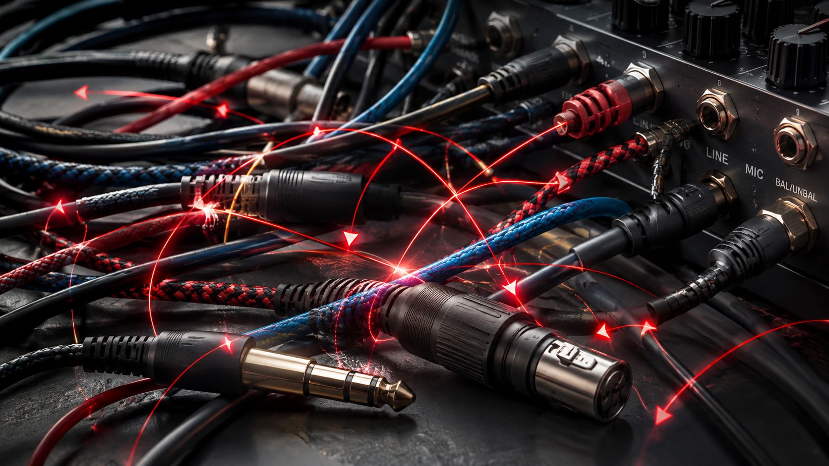
A boutique cable can't rescue a bad loop area. It can't magically give a noisy switch-mode wall wart a clean return path. It can't stop a long parallel run from acting like an antenna if the harness is laid out badly.
Practical rule: fix the route before you buy the remedy.
That's the part people don't want to hear because routing is boring and cables are sexy. But in a real hi-fi stack, boring is where the noise dies. If a phono stage hums, a streamer spits hash, or a DAC gets gray and pinched when the router wakes up, the first move is not “better cable.” The first move is “where is the coupling happening?”
A lot of EMI advice treats shielding, grounding, and filtering as interchangeable. They aren't. Shielding keeps fields out, grounding gives stray current a controlled return path, and filtering blocks unwanted frequencies before they ride into the signal chain. The win is not to make interference vanish. It's to push it below the floor where it stops annoying the signal.
Diagnose the Noise Before You Touch Anything
A fix without a measurement is a guess with a receipt. Before I move a single cable in a rack, I want a baseline that tells me what kind of noise I'm hearing and where it probably lives.
Start with the symptom, not the cure. A low hum that changes with volume or input selection usually points toward a grounding or loop problem. A sharper buzz, hiss, or gritty edge that gets worse near routers, chargers, or digital gear often smells like RF or switching noise. If the system coughs only when certain devices power up, you've probably found the trigger, even if you haven't found the exact path yet.
Use simple tools first. A handheld AM radio, a cheap loop probe, or even a careful sweep of the room can tell you where the ugly gets louder. You don't need lab theater to learn something useful. You need repeatability, and you need to know what changed.
The same logic applies if you're listening for the noise at the speaker, headphone output, or phono stage. Note whether the complaint is constant, intermittent, volume-dependent, or tied to a device waking up. Then write it down. That note is the baseline, and without it every later tweak turns into superstition.
For a deeper primer on what static sounds like and how it tends to show up in audio chains, I'd start with this guide to audio static symptoms and causes.
Read the fault, don't romanticize it
Here's the useful split.
- Ground-loop hum: low, steady, often tied to connected gear and cable paths.
- Switching hash: rougher and more wiry, often tied to power supplies, chargers, and digital boxes.
- Wireless spray: gets worse near radios, streamers, and crowded device clusters.
Once you can describe the fault cleanly, the fix stops being mystical. You're no longer “cleaning up the sound.” You're attacking a named coupling mechanism.
That sounds dry, but it's exactly how you keep from buying the wrong thing twice.
Ground Loops and the One Grounding Rule That Matters
Grounding is where people get loud and still talk past each other. The argument usually starts because they treat every frequency the same. Single-point grounding is the better default at lower frequencies, while multi-point grounding tends to work better at higher frequencies, because long shared ground paths stop acting like a clean reference once you get into RF. A grounding reference from OSHA makes the same basic point from the safety side, even if the audio application is different.
In hi-fi terms, the rack is not one magical ground. It is a topology. If you daisy-chain signal grounds through multiple boxes, you can build a loop antenna and give noise a private highway. If you star-ground the system cleanly, stray current gets one controlled place to go. Same word, different physics.
What usually works in a rack
Keep the return path obvious and short. Chassis-to-chassis links can help when they create a lower-impedance reference, but they can also create a loop if multiple ground references are already tied together somewhere else. That is why a “better ground wire” is usually a lazy diagnosis. The problem is more often the topology than the conductor.
For turntables, phono stages, DACs, and amps, the goal is simple. Do not let one component's return path wander through another component's signal ground if you can avoid it. Keep the chassis strategy coherent, keep the signal grounds from being daisy-chained by accident, and do not assume the rack rails themselves are harmless.
If you want a beginner-friendly refresher on how turntable grounding and placement can go sideways, I'd pair this with a basic turntable setup guide.
Practical rule: if the hum changes when you rearrange the chain, you are looking at topology, not tone.
The tendency to tighten a screw, swap a wire, and declare victory persists, and more often than not the loop moved a few inches. Sometimes that is enough. More often, the fix is making the return path shorter, cleaner, and less shared after you are done.
The FCC made EMI a mainstream compliance issue in 1979, when it imposed legal limits on emissions from digital equipment. That pressure pushed the industry toward the same core moves engineers still use now, shorter signal paths, better grounding, shielding, and cleaner filtering (TT Electronics EMI overview). The history matters because the physics never changed. The gear just got denser.
Cable Routing and Shielding as a Geometry Problem
Cables are the cheapest place to win, if you treat them like geometry instead of jewelry. The first fixes are almost always physical, not electrical. Keep interference-carrying conductors short, reduce parallel runs, increase separation between noisy and sensitive cables, and cross unavoidable power and signal paths at 90° (industrial noise reduction guidance).
That's not audiophile folklore. That's about coupling area. The more two conductors sit alongside each other, the easier it is for one to drag the other around by the collar. Twisted-pair cable helps because it improves magnetic-field immunity. Short motor leads help because they keep the antenna small. Filters help more when they sit close to the noise source, not stranded halfway across the enclosure.
Where shielded cable helps, and where it doesn't
Shielding is useful when it is a barrier. A technical summary describes metal cases, shielded cables, and Faraday cages as shielding methods, and it notes that the shield must be grounded in systems like shielded Ethernet cabling for protection to work as intended (EcoFlow EMI summary). Decorative shielding is just expensive wallpaper.
The trap is over-grounding by reflex. If you bond shields everywhere without thinking about the path, you can create multiple return routes and new loops. In practice, the shield should terminate where it belongs, not where your panic tells you to land it. For some runs, a single-end termination is the cleaner move. For others, the enclosure bond matters more than the cable itself.
A useful industrial rule of thumb says to aim for roughly 10 cm of separation per 10 m of parallel cable length when power and signal cables must run alongside each other (noise reduction guidance). Real hi-fi racks rarely need the full rule because they're small. Still, it gives you a sense of scale. If the power brick and the analog interconnect are kissing, that's bad geometry no matter how nice the cable jacket looks.
Keep the noisy run away from the victim first. Everything else comes after.
I've fixed more “mysterious” hum by moving a cable six inches than by swapping three premium cords. That's embarrassing for the cord aisle, but it's the truth.
Power Treatment and Component-Level Fixes Worth the Money
Once the layout is clean, the hardware layer starts to make sense. Power conditioners, isolation transformers, ferrite chokes, common-mode filters, and adapter swaps can help, but only when they match the noise path you found. A ferrite on a cable will not fix a ground loop. A conditioner will not cure Bluetooth spray. A nicer wall wart will not repair a bad return path.
The better question is simple, what is still leaking noise after the geometry is sorted out? If the answer is conducted noise on the power line, filtering can earn its keep. If the answer is high-frequency junk entering through a cable, a choke or better filtering near the entry point may help. If the problem is local RF crowding around the gear, placement usually beats another box.
For PCB and system design, the same order keeps showing up. Good layout first, then decoupling right at the power pins, then filtering near entry and exit points, then shielding where the field still escapes. That order holds because a small loop usually beats an expensive enclosure, and I have seen that in my own rack more than once.
The hardware that earns its rack space
Some parts are worth paying for because they address a specific coupling mechanism.
- Isolation transformers: useful when the mains path itself is carrying trouble and you need separation.
- Common-mode filters: useful when noise rides on both conductors together.
- Ferrite chokes: useful on cables where high-frequency trash is sneaking through.
- Filtered or linear supplies: useful when a noisy adapter is the actual source instead of just a bystander.
There is also a modern wrinkle here. Mixed RF environments are denser now, and classic shielding can stop helping once everything in the room is radiating, switching, and talking at once. The practical answer becomes more system-level, more about source control and coupling-path analysis, and less about wrapping everything in metal and hoping for the best.
For a concrete example of how power-stage behavior can shape the noise floor in a system, the case for a compact switching design is worth reading alongside this mono Class D amplifier note.
If I had to spend money in order, I would start with layout sanity, then buy the right filter, then choose the right supply. I would leave the boutique cable for after the hum is already gone.
Verify the Fix With a Before and After Trace
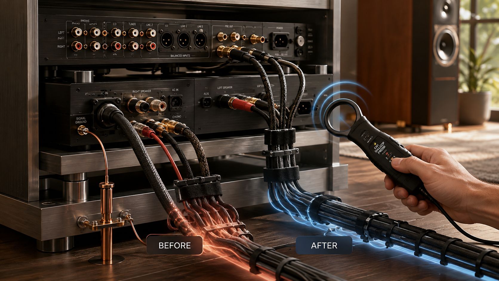
A fix you can't measure is a fix you can't trust. In audio, that usually means a story you're telling yourself because you wanted the tweak to work. I don't trust a “quieter” rack until I've re-run the same test and compared the result against the original baseline.
The method is simple. Use the same diagnostic you used before, the same listening position, the same cable routing, the same gain setting if you can manage it. Capture the after state. Then compare the time-domain behavior and, if you have it, the spectral view. You're looking for a real change in the fault, not just a prettier line on a screen.
What a real improvement sounds like
A useful fix usually changes the character of the noise, not just its presence. The hum drops. The hash loosens its grip. The background gets less nervous. Voices stop wearing that faint gritty edge that makes a good chain sound like it's trying too hard.
A fake win is different. The system may look quieter on paper, but it can also sound drier, flatter, or oddly polite. That's the trap of chasing a lower floor without listening for body, space, and decay. EMI reduction should remove interference, not bleach the life out of the recording.
Practical rule: trust the trace, then trust the ear.
If both agree, keep the change. If they disagree, don't rush to declare victory. Sometimes the measurement improved because you moved the problem somewhere less obvious. Sometimes your ear is hearing a different compromise. That's why the before trace matters. It gives you something to compare against instead of a memory.
I like notes here that are boring and specific. “Hum gone when streamer is off.” “Hash returns when power brick touches phono cable.” “Noise drops when the signal run is moved away from the wall wart.” That kind of sentence beats poetry every time.
The Short List of Fixes That Actually Move the Needle
Trace the coupling path.
Fix the ground topology.
Reroute the cables.
Cross at right angles when you must cross at all.
Then reach for filtering, ferrites, or shielding only where geometry can't finish the job.
Verify it with a measurement, not a vibe.
Most EMI problems are geometry problems wearing a price tag.
| EMI Fixes Ranked by Cost-to-Effect Ratio | Typical Cost | Symptom It Actually Addresses |
|---|---|---|
| Reroute cables and increase separation | Low | Hum, hash, and crosstalk from bad cable geometry |
| Fix ground topology | Low to medium | Ground-loop hum and shared-return noise |
| Move noisy wall warts and power bricks away from signal paths | Low | Grit, buzz, and RF spray in nearby audio stages |
| Add proper filtering near the entry point | Medium | Conducted noise riding in on power or signal lines |
| Use ferrite chokes on the right cable | Low to medium | High-frequency trash on specific cable runs |
| Upgrade to a better-isolated supply | Medium to high | Noise from a bad adapter or local supply pollution |
| Add shielding where the enclosure is genuinely weak | Medium to high | Radiated interference that geometry couldn't tame |
If your rack is still misbehaving after that pass, don't guess harder. Strip it back, trace it again, and fix the path you can prove. Then come back and tell the story to the next person who wants to buy the loudest fix in the room.
If you want more straight-shooting hi-fi troubleshooting like this, keep reading Supermarket Sound, and if your rack still has a noise problem, start with a baseline trace before you spend another dollar.

